Introduction to Standardized Tooling Instrument and Kinematic Components For precise location in gaging, tooling and scientific instruments
The fundamental kinematic mount is a specialized method of coupling two elements in a mechanical system. One element is usually fixed to the frame of the apparatus, and the other is portable or movable. In a well designed mount, the portable element can be removed and replaced or indexed with nanometric repeatability. The concept of the kinematic mount is to eliminate any or all of the six degrees of freedom between the two elements of the system without using any strenuous clamping or over constraint. These degrees of freedom are usually defined as the three straight axis-"X" axis, "Y" axis,"Z" axis and the rotational axis of pitch, yaw and roll. A large number of variations on the fundamental Kinematic design have been developed. The "classical" design uses three spherical points of contact (balls) that are usually incorporated into one of these elements.
The second element incorporates a vee groove, a conical cup and a plane surface. Some of the factors that limit the ultimate accuracy of a kinematic system are the extreme difficulties of generating high quality conical cups and vee grooves. These problems can be solved using our kinematic components. By substituting two of our high-quality cylinders for the vee grooves and three of our high-quality spheres for the cone, you can achieve orders of magnitude improvement in repeatability. A careful choice of material is required in order to avoid the problem of fretting. Fretting may occur due to the high elastic loads caused by the small contact areas characteristic of most kinematic designs. We have developed our product line around an excellent fret-resistant material. It is a through-hardened, high-chrome, high-carbon stainless steel.
Another excellent choice of material is tungsten carbide. It is very fret-resistant and has an extremely high rigidity (i.e., Young's Modulus of Elasticity). Since it is much more expensive, it is not as widely used. Because there is little or no movement between the elements of a kinematic mount, the same material can be used for all components without the usual problems of wear and galling. Although we manufacture an extensive and expanding line of standard kinematic components, we will also custom-manufacture unique high quality components to your specifications. These may be made of materials with special heat or corrosive-resistant properties, or with different magnetic or electrical characteristics. They may be tailored to fit ideally into your products. These include prismatic Vee-Blocks with optical-quality metal surfaces, Kelvin trihedral cups with optical-quality metal facets and cathedral or Gothic arch-vees with optical quality radii.
Heavy Duty Adjustable Kinematic Coupling
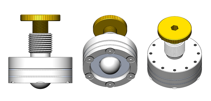 Adjustable Kinematic Coupling, three views
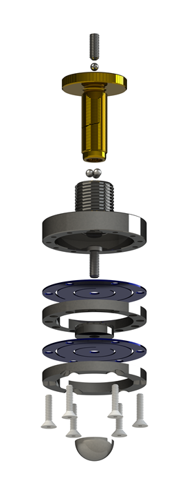 Adjustable Kinematic Coupling, exploded view
Making adjustments in the elevation, tip, or tilt of a kinematic platform has historically been a major problem without a good solution. The most common approach to adjusting changes in elevation was to mount a ball on the end of a fine-pitch threaded-shaft. The shaft and the ball rotate while the ball is in contact with the two faces of a mating vee-block. Rotating the threaded-shaft extended the ball, causing one corner of the kinematic platform to raise or lower depending on which direction the threaded shaft was rotated. But the very small area of contact of the ball with the flat surfaces of the vee-block resulted in extremely high Hertzian stresses.
The big problem with this design begins with the strong tendencies for these highly-stressed rotating surfaces to interact metallurgically with each other, causing spalling and then galling and ultimately fretting, with large craters developing from the rotation of the two parts against each other under load. Another problem with this design is that there is always going to be some clearance between the flanks of the male and female threads, leading to unreliable retention of the original position between the two kinematic platforms.
Still another major problem is that the axis of the ball and the axis of the thread will not be perfectly concentric, so the X and Y positions of the adjustable platform will be constantly changing their positions in complex patterns as the thread is rotated. Another approach to providing adjustability is to provide a long cylindrical tube with a very close fitting cylindrical shaft with a spherical end. This spherical end usually consists of a precision ball that is press-fit into a hole in the end of the shaft.
The entire accuracy of this device depends on the closeness of the fit between the inside and outside diameters of these two cylinders. If the fit is too close, they will cold weld and gall into an immovable structure. There must be lubricant between the two cylinders to keep them from galling. This lubrication-filled gap will slowly move around, shifting the X and Y axes of the upper platform. The adjustment up and down is usually made by a fine threaded member at the top of the assembly.
For this kind of device to work at all, the engagement of the internal and external cylinders must also be of a considerable length. By machining a key-way-like feature in one end it can be made so that it does not rotate as the adjustment is made, but again, there still must be clearance between the key and the key-way. What it comes down to is that this kind of design isn’t very good. It is much too long, it is expensive, there is stick and slip, and far too much backlash for any fine work, and the kinematic contact points are inexorably damaged by adjusting them.
The FlexaSphere Kinematic Coupling
We have now developed a totally new approach to adjustable kinematic couplings called the FlexaSphere, which solves all of these historical problems that have plagued adjustable kinematic couplings once and for all. With this new design, the ball does not rotate! Our device uses a standard ball size of .750-inch. The ball material is a 58-HRC hardened stainless-steel.
The ball has no backlash at all and it does not drift over time. The basic design is a dual diaphragm assembly that is driven by a large .500-inch diameter 40-threads-per-inch male-screw mounted in an extremely rigid steel housing. The new design is totally free from any form of hysteresis! The assembly is so extremely stiff, it is hard to even compare it with any other style of adjustable kinematic coupling.
The ball moves straight up and down, so the adjustment causes no shift in the X or Y axes of the platform. This new approach to adjusting kinematic couplings allow easy movement in micro-inch increments for more than a tenth of an inch (0.100”) total travel.
Superior Position-Locking
There is a serious question that must be addressed in the design of all adjustable kinematic couples, that is: How do you lock the adjustment-screw in place after the final setting is made?
One option is not to lock the screw at all, but to depend on the fine pitch thread to remain where it was set. Using this approach, just a little vibration and your settings are lost. The most common locking mechanism is the jam nut. Using this method, there is a second nut that is somehow tightened against the end of the main body thread, stopping all rotation. A big problem here is that the clamping action always significantly alters the desired setting.
Another much better method is to split one end of the threaded-tube and tighten a tapered nut over it to compress the female thread against the adjustable male-threaded element, until it stops all rotation. This method is good, but it adds useless length to the overall dimensions of the assembly, it is bulky, it is expensive to produce, and it requires a high force to rotate the locking nut.
Our technique used on the FlexaSphere is to expand the outside-diameter of the male-threaded member against the female-threaded rigid housing. This locking method requires almost no torque. It locks all motion, making it impossible to move the setting. It does not change any of the settings, not even micro-inches. Finally, this clamping method is perpetual, there is no wear on any of the elements.
Flexacanoe: A Coupling for Higher Loads
An additional giant leap forward in kinematic design can be achieved by combining the adjustability of the FlexaSphere-750 in conjunction with our .750" Subminiature Canoe Sphere (CS-750-SM).
Because the FlexaSphere can produce precision linear movement without rotation, a canoe-sphere, capable of enormous load-carrying capacity compared to a ball, can be used instead, producing the FlexaCanoe.
Need Even More Load Capacity?
We are now producing a 4" diameter version called the Flexcanoe-2000, which uses our most popular canoesphere, the 2" diameter CS-2000-CPM in the same basic FlexaSphere design, allowing it to bear several thousand pounds. With the Flexcanoe-2000, our canoesphere can now be positioned in microinches at will.
| Part Number |
Description |
Contact Element |
Price |
| FlexaSphere-750 |
2" diameter with .750" Truncated ball |
.750" Stainless Truncated Ball |
$135 |
| FlexCanoe-750 |
2" diameter with .750 Canoesphere |
CS-750-SM Canoe |
$392 |
| FlexCanoe-2000 |
4" diameter with 2" Canoesphere |
CS-2000-CPM |
$405 |
Heavy Duty Adjustable Kinematic Coupling
 Adjustable Kinematic Coupling, three views
 Adjustable Kinematic Coupling, exploded view
Making adjustments in the elevation, tip, or tilt of a kinematic platform has historically been a major problem without a good solution. The most common approach to adjusting changes in elevation was to mount a ball on the end of a fine-pitch threaded-shaft. The shaft and the ball rotate while the ball is in contact with the two faces of a mating vee-block. Rotating the threaded-shaft extended the ball, causing one corner of the kinematic platform to raise or lower depending on which direction the threaded shaft was rotated. But the very small area of contact of the ball with the flat surfaces of the vee-block resulted in extremely high Hertzian stresses.
The big problem with this design begins with the strong tendencies for these highly-stressed rotating surfaces to interact metallurgically with each other, causing spalling and then galling and ultimately fretting, with large craters developing from the rotation of the two parts against each other under load. Another problem with this design is that there is always going to be some clearance between the flanks of the male and female threads, leading to unreliable retention of the original position between the two kinematic platforms.
Still another major problem is that the axis of the ball and the axis of the thread will not be perfectly concentric, so the X and Y positions of the adjustable platform will be constantly changing their positions in complex patterns as the thread is rotated. Another approach to providing adjustability is to provide a long cylindrical tube with a very close fitting cylindrical shaft with a spherical end. This spherical end usually consists of a precision ball that is press-fit into a hole in the end of the shaft.
The entire accuracy of this device depends on the closeness of the fit between the inside and outside diameters of these two cylinders. If the fit is too close, they will cold weld and gall into an immovable structure. There must be lubricant between the two cylinders to keep them from galling. This lubrication-filled gap will slowly move around, shifting the X and Y axes of the upper platform. The adjustment up and down is usually made by a fine threaded member at the top of the assembly.
For this kind of device to work at all, the engagement of the internal and external cylinders must also be of a considerable length. By machining a key-way-like feature in one end it can be made so that it does not rotate as the adjustment is made, but again, there still must be clearance between the key and the key-way. What it comes down to is that this kind of design isn’t very good. It is much too long, it is expensive, there is stick and slip, and far too much backlash for any fine work, and the kinematic contact points are inexorably damaged by adjusting them.
The FlexaSphere Kinematic Coupling
We have now developed a totally new approach to adjustable kinematic couplings called the FlexaSphere, which solves all of these historical problems that have plagued adjustable kinematic couplings once and for all. With this new design, the ball does not rotate! Our device uses a standard ball size of .750-inch. The ball material is a 58-HRC hardened stainless-steel.
The ball has no backlash at all and it does not drift over time. The basic design is a dual diaphragm assembly that is driven by a large .500-inch diameter 40-threads-per-inch male-screw mounted in an extremely rigid steel housing. The new design is totally free from any form of hysteresis! The assembly is so extremely stiff, it is hard to even compare it with any other style of adjustable kinematic coupling.
The ball moves straight up and down, so the adjustment causes no shift in the X or Y axes of the platform. This new approach to adjusting kinematic couplings allow easy movement in micro-inch increments for more than a tenth of an inch (0.100”) total travel.
Superior Position-Locking
There is a serious question that must be addressed in the design of all adjustable kinematic couples, that is: How do you lock the adjustment-screw in place after the final setting is made?
One option is not to lock the screw at all, but to depend on the fine pitch thread to remain where it was set. Using this approach, just a little vibration and your settings are lost. The most common locking mechanism is the jam nut. Using this method, there is a second nut that is somehow tightened against the end of the main body thread, stopping all rotation. A big problem here is that the clamping action always significantly alters the desired setting.
Another much better method is to split one end of the threaded-tube and tighten a tapered nut over it to compress the female thread against the adjustable male-threaded element, until it stops all rotation. This method is good, but it adds useless length to the overall dimensions of the assembly, it is bulky, it is expensive to produce, and it requires a high force to rotate the locking nut.
Our technique used on the FlexaSphere is to expand the outside-diameter of the male-threaded member against the female-threaded rigid housing. This locking method requires almost no torque. It locks all motion, making it impossible to move the setting. It does not change any of the settings, not even micro-inches. Finally, this clamping method is perpetual, there is no wear on any of the elements.
Flexacanoe: A Coupling for Higher Loads
An additional giant leap forward in kinematic design can be achieved by combining the adjustability of the FlexaSphere-750 in conjunction with our .750" Subminiature Canoe Sphere (CS-750-SM).
Because the FlexaSphere can produce precision linear movement without rotation, a canoe-sphere, capable of enormous load-carrying capacity compared to a ball, can be used instead, producing the FlexaCanoe.
Need Even More Load Capacity?
We are now producing a 4" diameter version called the Flexcanoe-2000, which uses our most popular canoesphere, the 2" diameter CS-2000-CPM in the same basic FlexaSphere design, allowing it to bear several thousand pounds. With the Flexcanoe-2000, our canoesphere can now be positioned in microinches at will.
| Part Number |
Description |
Contact Element |
Price |
| FlexaSphere-750 |
2" diameter with .750" Truncated ball |
.750" Stainless Truncated Ball |
$135 |
| FlexCanoe-750 |
2" diameter with .750 Canoesphere |
CS-750-SM Canoe |
$392 |
| FlexCanoe-2000 |
4" diameter with 2" Canoesphere |
CS-2000-CPM |
$405 |
Heavy Duty Adjustable Kinematic Coupling
 Adjustable Kinematic Coupling, three views
 Adjustable Kinematic Coupling, exploded view
Making adjustments in the elevation, tip, or tilt of a kinematic platform has historically been a major problem without a good solution. The most common approach to adjusting changes in elevation was to mount a ball on the end of a fine-pitch threaded-shaft. The shaft and the ball rotate while the ball is in contact with the two faces of a mating vee-block. Rotating the threaded-shaft extended the ball, causing one corner of the kinematic platform to raise or lower depending on which direction the threaded shaft was rotated. But the very small area of contact of the ball with the flat surfaces of the vee-block resulted in extremely high Hertzian stresses.
The big problem with this design begins with the strong tendencies for these highly-stressed rotating surfaces to interact metallurgically with each other, causing spalling and then galling and ultimately fretting, with large craters developing from the rotation of the two parts against each other under load. Another problem with this design is that there is always going to be some clearance between the flanks of the male and female threads, leading to unreliable retention of the original position between the two kinematic platforms.
Still another major problem is that the axis of the ball and the axis of the thread will not be perfectly concentric, so the X and Y positions of the adjustable platform will be constantly changing their positions in complex patterns as the thread is rotated. Another approach to providing adjustability is to provide a long cylindrical tube with a very close fitting cylindrical shaft with a spherical end. This spherical end usually consists of a precision ball that is press-fit into a hole in the end of the shaft.
The entire accuracy of this device depends on the closeness of the fit between the inside and outside diameters of these two cylinders. If the fit is too close, they will cold weld and gall into an immovable structure. There must be lubricant between the two cylinders to keep them from galling. This lubrication-filled gap will slowly move around, shifting the X and Y axes of the upper platform. The adjustment up and down is usually made by a fine threaded member at the top of the assembly.
For this kind of device to work at all, the engagement of the internal and external cylinders must also be of a considerable length. By machining a key-way-like feature in one end it can be made so that it does not rotate as the adjustment is made, but again, there still must be clearance between the key and the key-way. What it comes down to is that this kind of design isn’t very good. It is much too long, it is expensive, there is stick and slip, and far too much backlash for any fine work, and the kinematic contact points are inexorably damaged by adjusting them.
The FlexaSphere Kinematic Coupling
We have now developed a totally new approach to adjustable kinematic couplings called the FlexaSphere, which solves all of these historical problems that have plagued adjustable kinematic couplings once and for all. With this new design, the ball does not rotate! Our device uses a standard ball size of .750-inch. The ball material is a 58-HRC hardened stainless-steel.
The ball has no backlash at all and it does not drift over time. The basic design is a dual diaphragm assembly that is driven by a large .500-inch diameter 40-threads-per-inch male-screw mounted in an extremely rigid steel housing. The new design is totally free from any form of hysteresis! The assembly is so extremely stiff, it is hard to even compare it with any other style of adjustable kinematic coupling.
The ball moves straight up and down, so the adjustment causes no shift in the X or Y axes of the platform. This new approach to adjusting kinematic couplings allow easy movement in micro-inch increments for more than a tenth of an inch (0.100”) total travel.
Superior Position-Locking
There is a serious question that must be addressed in the design of all adjustable kinematic couples, that is: How do you lock the adjustment-screw in place after the final setting is made?
One option is not to lock the screw at all, but to depend on the fine pitch thread to remain where it was set. Using this approach, just a little vibration and your settings are lost. The most common locking mechanism is the jam nut. Using this method, there is a second nut that is somehow tightened against the end of the main body thread, stopping all rotation. A big problem here is that the clamping action always significantly alters the desired setting.
Another much better method is to split one end of the threaded-tube and tighten a tapered nut over it to compress the female thread against the adjustable male-threaded element, until it stops all rotation. This method is good, but it adds useless length to the overall dimensions of the assembly, it is bulky, it is expensive to produce, and it requires a high force to rotate the locking nut.
Our technique used on the FlexaSphere is to expand the outside-diameter of the male-threaded member against the female-threaded rigid housing. This locking method requires almost no torque. It locks all motion, making it impossible to move the setting. It does not change any of the settings, not even micro-inches. Finally, this clamping method is perpetual, there is no wear on any of the elements.
Flexacanoe: A Coupling for Higher Loads
An additional giant leap forward in kinematic design can be achieved by combining the adjustability of the FlexaSphere-750 in conjunction with our .750" Subminiature Canoe Sphere (CS-750-SM).
Because the FlexaSphere can produce precision linear movement without rotation, a canoe-sphere, capable of enormous load-carrying capacity compared to a ball, can be used instead, producing the FlexaCanoe.
Need Even More Load Capacity?
We are now producing a 4" diameter version called the Flexcanoe-2000, which uses our most popular canoesphere, the 2" diameter CS-2000-CPM in the same basic FlexaSphere design, allowing it to bear several thousand pounds. With the Flexcanoe-2000, our canoesphere can now be positioned in microinches at will.
| Part Number |
Description |
Contact Element |
Price |
| FlexaSphere-750 |
2" diameter with .750" Truncated ball |
.750" Stainless Truncated Ball |
$135 |
| FlexCanoe-750 |
2" diameter with .750 Canoesphere |
CS-750-SM Canoe |
$392 |
| FlexCanoe-2000 |
4" diameter with 2" Canoesphere |
CS-2000-CPM |
$405 |
The Subminiature Canoe Sphere - .750" Canoe Sphere
Part#: CS-750-SM
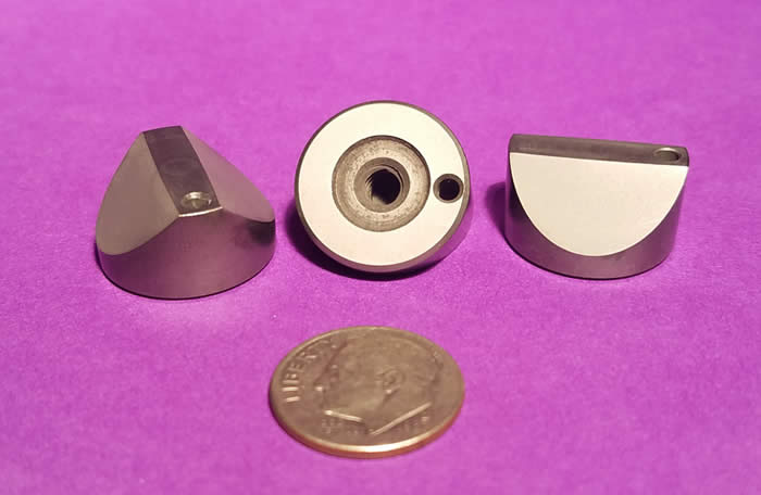
We have developed a 3/4" diameter Canoe Sphere (19.05mm) for even smaller applications. These have a spherical radius ground and lapped into its contact faces of approximately 10" (.25 m). We have built a unique, single-purpose machine that precision-grinds the desired radius, and only that radius, into this part. This part features the same ultra-fine-grain, high-chrome, high-carbon, 440C stainless steel hardened to 58 HRC minimum as our other Canoe-Spheres.
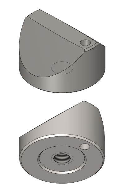
It uses a surface-mounted design with a blind hole on the bottom with a 10-24 thread, clamped from the rear, with a single .09375" alignment pin hole to the side. The bottom is also ground and lapped flat. It can be easily paired with our Surface-Mounted Veeblock (part # VB-75-SM), or our Mid-Size Post-Mounted Veeblock (part # VB-375-CPM).
This part (#CS-750-SM) is available for an investment of $145.50.
Plain Flat Kinematic Component
For many years past, the trend in kinematic coupling designs has shunned the classical conical cup, vee block and flat plane as described by both Maxwell and Lord Kelvin in separate publications in the late eighteen-hundreds. This reluctance was based on the great difficulty of generating very high quality conical and vee block surfaces.
Standardized kinematic components are now available that solve these age old quality limitations. Availability of these components has rekindled interest in the classical designs with the many advantages that are offered by the diverse components. An outstanding example of these advantages is the ability of an axis to pivot with unheard of accuracy along the line axis between the Conical Cup and the Vee Block.
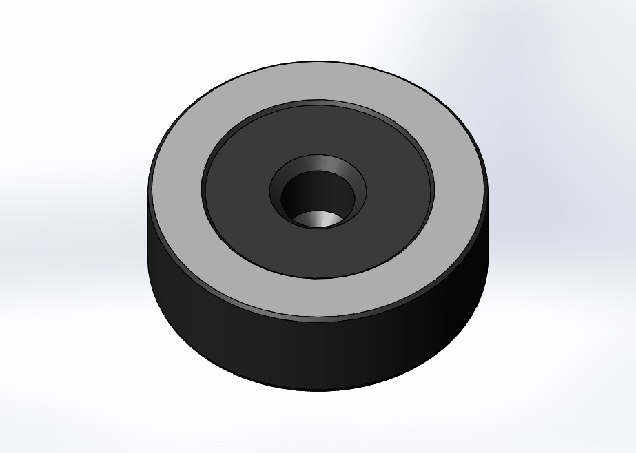
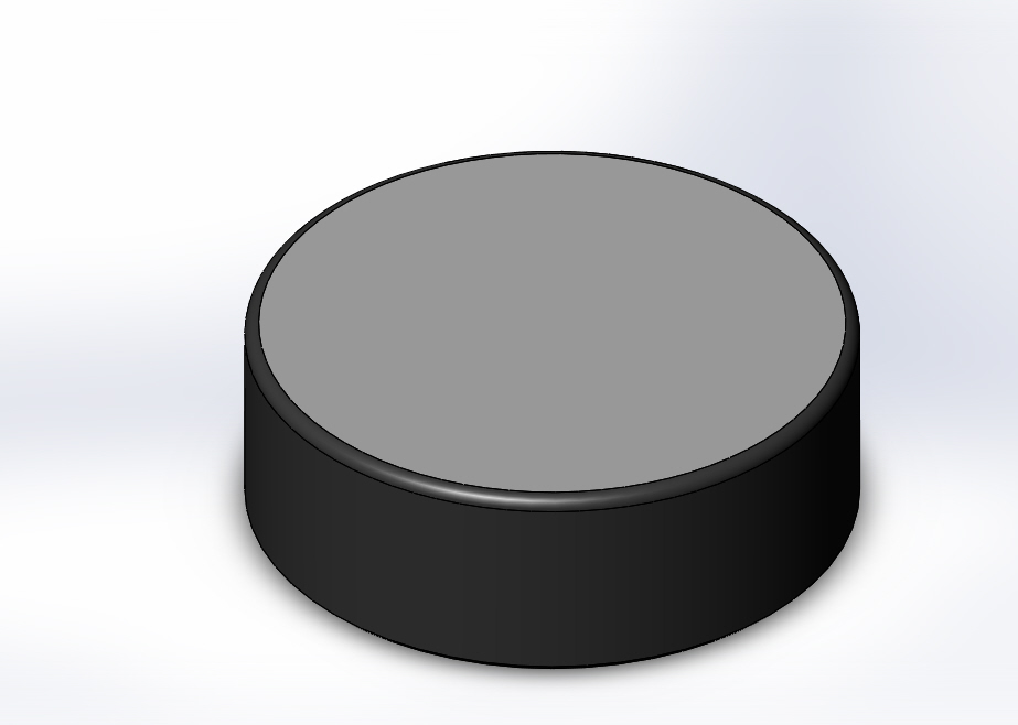
Figure: F-875-SM
Among the kinematic purists out there, this will end up as a button pushing opportunity. If the Vee Block is pointed at the bisector of the kinematic axis of the coupling, the line axis of the pivot could undulate because the two tangent contacts are not on the pivot axis. If on the other hand, the Vee Block is pointed parallel to the axis, we want to depict that we are no longer in strict compliance with kinematic principles.
If there is one thing that we have learned through the years, is that kinematics in general are very forgiving. A line of standardized flat components are available to go along with the conical cups and the more sophisticated components like the Rose Bud and Prismatic Components. The design of the first of the standard flat devices is for everyday applications. It is a disk made of micro "rained" stainless steel that is hardened to 58 HRC minimum. These disks are ground parallel and the working surface is lapped flat with a 2 microinch (.05 micrometer) Ra surface quality. There is a blind threaded hole in the back surface to hold them on the Kinematic Platform.
Special Order Only
We will custom manufacturer any special design required to fill specific customer needs for corrosion resistance and magnetic or electrical properties. The third option has the same design features as the standard flat devices except it has a precision ground cylindrical boss that provides excellent locate-ability. For premium applications, there is a steel disk that is threaded on the outside diameter. There is a smaller tungsten carbide disk glued in the center of the working face. This carbide disk is lapped flat with 1 microinch (.025 micrometer) Ra surface quality. Tungsten Carbide is the stiffest, hardest, commercially available material, with a Young's Modulus of Elasticity of 98,000,000 PSI and a hardness of 91 HRA.
This thread on the disk can be used as an adjustment or to lock the device in place. As an alternative, it can simply be permanently glued into an oversize counterbore. There are four holes drilled in the top face. This allows adjustment up and down by rotating it with a special Spanner Wrench, Part Number SW -1.
Plain Flat Kinematic Component
For many years past, the trend in kinematic coupling designs has shunned the classical conical cup, vee block and flat plane as described by both Maxwell and Lord Kelvin in separate publications in the late eighteen-hundreds. This reluctance was based on the great difficulty of generating very high quality conical and vee block surfaces.
Standardized kinematic components are now available that solve these age old quality limitations. Availability of these components has rekindled interest in the classical designs with the many advantages that are offered by the diverse components. An outstanding example of these advantages is the ability of an axis to pivot with unheard of accuracy along the line axis between the Conical Cup and the Vee Block.
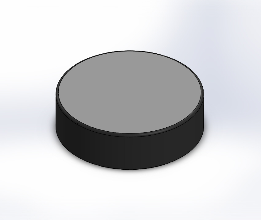
Figure: F-112-SM
Among the kinematic purists out there, this will end up as a button pushing opportunity. If the Vee Block is pointed at the bisector of the kinematic axis of the coupling, the line axis of the pivot could undulate because the two tangent contacts are not on the pivot axis. If on the other hand, the Vee Block is pointed parallel to the axis, we want to depict that we are no longer in strict compliance with kinematic principles.
If there is one thing that we have learned through the years, is that kinematics in general are very forgiving. A line of standardized flat components are available to go along with the conical cups and the more sophisticated components like the Rose Bud and Prismatic Components. The design of the first of the standard flat devices is for everyday applications. It is a disk made of micro "rained" stainless steel that is hardened to 58 HRC minimum. These disks are ground parallel and the working surface is lapped flat with a 2 microinch (.05 micrometer) Ra surface quality. There is a blind threaded hole in the back surface to hold them on the Kinematic Platform.
Special Order Only
We will custom manufacturer any special design required to fill specific customer needs for corrosion resistance and magnetic or electrical properties. The third option has the same design features as the standard flat devices except it has a precision ground cylindrical boss that provides excellent locate-ability. For premium applications, there is a steel disk that is threaded on the outside diameter. There is a smaller tungsten carbide disk glued in the center of the working face. This carbide disk is lapped flat with 1 microinch (.025 micrometer) Ra surface quality. Tungsten Carbide is the stiffest, hardest, commercially available material, with a Young's Modulus of Elasticity of 98,000,000 PSI and a hardness of 91 HRA.
This thread on the disk can be used as an adjustment or to lock the device in place. As an alternative, it can simply be permanently glued into an oversize counterbore. There are four holes drilled in the top face. This allows adjustment up and down by rotating it with a special Spanner Wrench, Part Number SW -1.