Ball Gage Technical Information Sheet
The Ball Plug Gage, Introduction
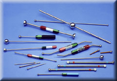 Bal-tec Ball Gages
Using a ball mounted on a stem or handle to evaluate the diameter of a cylindrical hole is a widely used commercial process. The first question that must be answered in evaluating any measuring process is, "just what is the fundamental premise for the methodology?" To be reliable, every dimensional measuring process must be directly traceable to a fundamental principal of physics. The fundamental definition for the diameter of a sphere is a geometric figure with all points on the periphery equidistant from a central point.
This is the pedigree for the use of the Ball Plug Gage. A Ball Plug Gage will absolutely measure the true cylindrical diameter of any hole. If a ball of a well known diameter will pass through an internal cylindrical diameter, we can be absolutely sure that this internal cylinder is at least as large as that ball is in diameter. A lack of cylindrisity does not influence the ball plug gage's ability to measure true cylindrical diameter. Even if a cylindrical hole is bent or cambered, a ball gage will still faithfully measure the true cylindrical diameter of that hole.
A factor that is always involved in making dimensional measurements by physical contact is the surface quality of both the gaging body and that of the subject part. Physical contact between the surface of a Ball Plug Gage and the internal cylinder that it is measuring is strictly limited to an extremely narrow line of contact. This very narrow line leads to almost no friction, so that the ball literally falls through the hole. The fundamental nature of the physical process used to manufacture precision balls automatically gives the ball an ideal gaging surface that is less than 1.5 micro inches RA. During the ball making process, a group of ball blanks are rolled between two plates in the presence of abrasive slurry. This lapping process creates the micro inch quality surface.
Attaching the Stem to the Ball
Attaching the precision gage ball to the stem or handle of a Ball Plug Gage presents several problems. The ball can not be brazed or soft soldered on the stem, because the heat will change the size of the ball and drive it out of round. An excellent solution for attaching the ball is to glue the stem into a small diameter deep hole.
The 62HRC hardness of the gage ball makes it much too hard for conventional drilling. The problem of drilling an acceptable mounting hole in the gage ball can be solved by using modified Electrical Discharge Machining techniques. The first step in this process is to use a super dielectric or electrolytes in the EDM machines. This dielectric is made by emulsifying silicon oil and distilled water with a 900 watt ultrasonic cavitron. This combination of distilled water and silicon oil has an extreme resistivity of over eighteen million ohms per square centimeter.
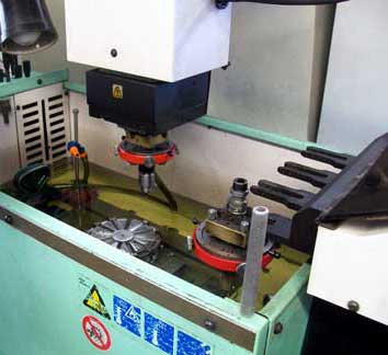 EDM Machine in Action at Bal-tec
The high specific heat of the water in the emulsion carries away the heat generated by the electrical discharge, without it causing any distortion of the gage ball. The frequency of the electric discharge current is held very high, so there are literally millions of very small sparks that cut the hole. After the difficult job of cleaning the EDM'ed hole is accomplished, a pre-machined stem is glued in the hole in the ball. For this task, an extreme strength ceramic filled epoxy resin is used.
Nothing is simple: A test sample from every batch of the epoxy glue mix must be tested for hardness and tensile strength. These tests are required because we have had failures due to the very complex glue chemistry, and we will not risk sending defective products to our customers.
A Ball Plug Gage Used as a Calibration Standard
The very best setting master for calibration the diameter of other precision balls is a calibrated "Master Ball Plug Gage." The traceable uncertainty of the absolute size of our Ball Plug Gages is in the low micro inches. By using a master setting standard with the same geometry and the same physical properties as the balls to be measured, the most accurate possible comparison can be made. (Ball Gage Setting Master). When trying to calibrate a spherical test part with a setting master that is a flat parallel gage block, or a cylindrical pin gage, the differences in geometry of the master and the spherical ball will lead to vast transfer errors.
Bent Stems or Handles
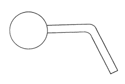 Ball Gage with a Bent Stem
The Versatility of Ball Plug Gages can be dramatically improved, for certain applications, by bending the stem so that the gage ball is applied to the test part at other than right angles, to the handle. If a simple sketch providing the stem length and the angle is provided, we can supply the gage pre bent and ready to use.
Really Bent Stems
There are times when the stem that holds the gage ball needs to be bent up down and all around, literally. In this case the stem material needs to be dead soft "annealed," mild steel. For this very special application, the stem material must be specified as dead soft annealed wire when placing the order.
The Cylindricized Ball Plug Gage
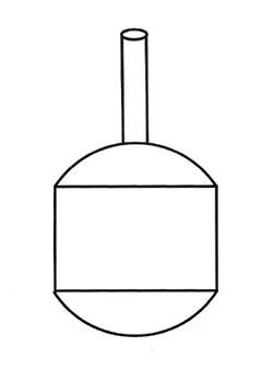 Cylindricized Ball Plug Gage
The spherical surface to be measured is sometimes down in the bottom of a restricted area. Reaching the surface to be measured requires that the major diameter of the Ball Plug Gage have a cylindrical section ground away. Even though this design is common place, every one of these gages must be custom made. The Cylidricized Ball Gage is also commonly used without a handle. Dimensions are commonly measured over the top end of the remaining ball. When the Cylindricized Ball Gage is used without a handle, the size and serial number is laser etched on the cylindrical diameter.
Internal Spherical Measurement
Measuring an Internal Spherical Cup
The most widely used method for measuring, both the size and the sphericity of an internal sphere is to use a Ball Plug Gage as a bluing master. The bluing technique consists of applying a very thin coat of Prussian Bluing to the test part or to the Ball Plug Gage and then rubbing the test part and the Ball Plug Gage together lightly. Prussian bluing is a deep dark blue pigment suspended in an oily base. Prussian Blue has nothing to do with Blue DYKEM®. Prussian Bluing is supplied in a small metal dispensing tube.
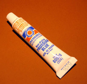 Tube of Prussian Blue
A little Prussian Bluing will go a long way, use it sparingly. Tubes of Prussian Blue are available as our part number BL-960. Prussian Bluing will stain anything that it touches, including your fingers. A good cleaning agent for Prussian Bluing is Isopropyl
Alcohol. Small amounts of Isopropyl Alcohol are available from any drug store, where it is sold as Rubbing Alcohol.
Isopropyl alcohol is flammable, so it must be used with great care. When using the Bluing technique, there are two general approaches:
For method number one, you put a light coat of Prussian Bluing on the test part and then use the Ball Plug Gage to wipe the bluing off. This is the technique that is usually used to inspect ball bearing race ways.
For method number two, which is sometimes called printing, the Prussian Bluing is applied to the Ball Plug Gage and then transferred to the test part by rubbing them lightly together. This printing technique is the one that is usually used for evaluating internal spherical surfaces. When using the technique of transferring Prussian Bluing to the test part from the Ball Plug Gage, it is highly recommended that a satin finished Ball Plug Gage be used.
A Satin finished surface will hold a nice even, very thin layer of Prussian Bluing, while the usual shiny, slippery lapped surface, of a standard ball, will have a splotchy, thicker layer. After the satin finished Ball Plug Gage is very lightly coated with Prussian Bluing, the Ball Plug Gage is placed into the spherical cup and lightly rubbed and indexed.
- If the bluing hits at the very top rim of the spherical cup, then the spherical cup is smaller than the ball.
- If the bluing hits at the very bottom ring of the spherical cup, then the spherical cup is larger than the ball.
- If the bluing covers the entire surface of the spherical cup, then the ball is the same radius as the cup.
It is very hard to machine the spherical cup exactly the right radius so tolerances are often spelled out in the percentage of the spherical surface that blues in I.E. the spherical surface must blue into x.xxx diameter Ball Plug Gage 80%. Another approach is that the spherical cup must be larger than one ball size and smaller than another. The danger of this type of tolerancing is that the surface of the cup may be grossly out of sphericity but still measure good. Using the tolerancing that the ball must blue into the sphere a given percent is by far the best tolerancing approach.
The Length of the Ball Gage Stem
The standard length of the stem or handle on a Ball Plug Gage is three inches ( 76mm ), but a stem of any desired length can be provided at little or no increase in cost.
See the "Snake Ball Gage" as an extreme, example of the stem length.
Measuring Cross Holes with a Ball Plug Gage
The Ball Plug Gage has two big advantages over any other gage for this chore. The first is that the Ball Plug Gage will enter a hole at any angle and automatically self align to pass through the hole, and the second is that the small diameter stem can be bent at an angle so that the ball will enter the hole nearly perpendicular. The Ball Plug Gage makes the measurement of cross holes at any angle to the walls of a part routine instead of nearly impossible.
Measuring Cross Race Curve of Antifriction Bearings
A Ball Plug Gage is the ideal tool to use for measuring the cross race curve of ball bearings. It is standard industry practice to evaluate both the actual radius and the geometric quality of antifriction bearing races, with a Ball Plug Gage. Prussian blue is a dark blue pigment suspended in an oily base. Prussian bluing has nothing to do with Blue DYKEM®. Prussian Bluing is supplied in a small metal dispensing tube. Tubes of Prussian Bluing are available as our part number BL-960. The first step in measuring the cross race curve of the bearing race is to apply a very thin coat of "Prussian blue" to the surface of the bearing race way. The second step is to use the Ball Plug Gage to wipe off the Prussian bluing.
If the cross race curve of the bearing race is exactly the same radius of curvature as the Ball Plug Gage, the ball will wipe off all of the "Prussian Blue" and the entire width of the raceway will have a silvery metallic look. If the cross race curve of the bearing race, is larger than the radius of the Ball Plug Gage, the ball will wipe all of the Prussian blue off of the bottom or center of the bearing race and it will leave a gradually darker blue stripe going up either side, of the bearing race. If the radius of the bearing race way is smaller than the Ball Plug Gage, the ball will wipe all of the bluing off the upper rims of the raceway leaving, two silvery stripes at the top with a gradually darker blue stripe at the bottom.
In addition to the Ball Plug Gage's ability to measure the exact radius of the cross race curve, it will accurately depict the regularity of the cross race curve. The sphericity of the Ball Plug Gage is almost perfect, so it will accurately indicate variations in the cross race curve as indicated by the blueness of the pattern left in the raceway by the Prussian Blue. Although the values are somewhat subjective, by using a series of different diameter Ball Plug Gages very definitive results can be determined. We have used this technique with a large number of Ball Plug Gages to provide more reliable data on cross race curve than could be produced by all of the machinery and personnel in a large bearing metrology lab. Extracting reliable data on the quality of the cross race curve of antifriction bearings is difficult.
Measuring Fragile Parts with a Ball Plug Gage
The most delicate, fragile parts can be safely evaluated with Ball Plug Gages. There is a very gradual engagement between the Ball Plug Gage and the part as the gage is brought into physical contact with the test part, and then the same gradual disengagement as the gage is removed. The non destructive nature of using a Ball Plug Gage is one of the outstanding properties of this device.
At a recent trade show, we learned of couple of excellent examples of this property. In the first case, a customer rejected a large order of a precision aluminum part. The flat surface adjacent to a very precise hole was all dinged up. This damage was done, by an inspector trying to get a cylindrical plug gage into the hole. All of these parts had to be fly cut a second time to correct the problem. In the second case, $5,000 worth of precise orifices had been scrapped by an inspector who used a cylindrical plug gage to measure the diameter of the narrow orifice, instead of the Ball Plug gage that was specified on the operation procedure.
A Handle for the Ball Plug Gage
Unless there are special needs, we supply a standard AGS (American Gage Society) design handle for our Ball Plug Gages. This handle consists of hexagonal aluminum tube with a hexagonal, threaded cap, on the end. The stem that the ball is mounted on is held in place by a collapsible bronze bushing. When the hexagonal aluminum cap is rotated clockwise, it compresses the bronze bushing thus locking the stem of the ball plug gage rigidly in place. The hexagonal aluminum caps are color anodized green for the GO end of the gage and red for the NO GO end of the gage.
Ball Plug Gages are most often supplied in a dual configuration, with a GO Ball Plug Gage on one end and a NO GO Ball Plug Gage on the other end. We also have these gage handles available in single ended configurations. The size of each ball plug gage is engraved into the handle of the gage. A nominal amount of additional information will be engraved on the handle at no additional cost. If an extensive amount of data must be engraved, it will require "Laser Marking" which may require a small surcharge.
Material for Ball Plug Gages
The conventional material used to manufacture Ball Plug Gages is a chromium alloy bearing quality steel. This very high carbon alloy steel is hardened to 62 H.R.C. (Hardness Rockwell "C scale"). This material is very stiff. It has a Young's modulus of elasticity of 30,000,000 PSI and a Poisson's ratio of 0.23. For some heavy use applications, the balls on the Ball Plug Gages are made of extremely hard, wear resistant, tungsten carbide. When tungsten carbide balls are used, the balls are usually brazed on to the stem. Ball Plug Gages made with tungsten carbide balls are available in the same high quality as the chrome steel balls.
Measuring Out of Round Holes
The holes that are used to hold fasteners in modern aircraft must be inspected for out of roundness. The simple test used for this evaluation is to rotate a No Go Ball Plug Gage that has two parallel ground flats, in the mouth of each hole. If the hole is out of round, the No Go Ball Plug Gage will fall through the out of round hole.
Measuring Shallow and Extremely Shallow Bores and Counter Bores
By removing the end of a Ball Plug Gage almost to its centerline, it can be used to very accurately measure bores and counter bores that are extremely shallow. The go Ball Plug Gage makes a very distinct click when entering the shallow hole, so that determining acceptable and not acceptable parts is a very black and white situation. The amount of centerline overhang must be kept to a minimum on the no go gage.
Rod End Bearings Measured with a Ball Plug Gage
A modified Ball Plug Gage is the best way to evaluate the internal spherical diameter of Rod End bearings. This modified Ball Plug gage, consists of a standard gage with two flats machined parallel to the stem or handle. These flats are machined so that the remaining sphere will safely enter the loading slot of the rod end bearing. A "go" and "no go" set of these modified Ball Plug Gages is required.
The Snake Ball Plug Gage
Measuring the Inside Diameter of Tubing and Pipe with a Ball Plug Gage.
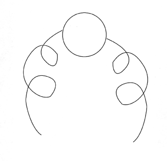 Snake Ball Gage
A simple solution for measuring the diameter of the full length of a piece of tubing or pipe is to pass a ball of known diameter through the diameter that is to be evaluated. The conduit to be evaluated can be straight, all bent up or full of joints, it doesn't matter. Previously, they used what was called the "puff test," for conduits on U.S. Navy submarines. This test consisted of putting a minimum sized ball that should easily pass through a pipe or tube in one end of each pipe or tube and then applying a few pounds of air pressure.
This puff of low pressure air would send the ball speeding through the tube and out the other end. This procedure went on for some years, until one day a ball got jammed in a tube down in the guts of a submarine. They had no idea where the ball was. It took days to cut out the entire piece of tubing and replace it.
When we were approached for a solution to this new dilemma, we quickly invented the "Snake Ball." This simple device has a continuous wire or cable going all the way through the center of the ball and coming out both sides. Using the Snake Ball, you are able to pull the ball into the tube and then you can pull it back out, all very inexpensively and with complete reliability.
For some fussy applications we provide an additional smaller diameter ball on the very ends of the wire. This provides a smoother passage of the wire past the joints in the conduit. For some applications with delicate surfaces, we supply the "Snake Ball" with wire cable that is plastic covered.
The Stem Material For Ball Plug Gages
The stem material used to hold the gage ball is typically drawn and straightened, mild steel. The Young's modulus of elasticity or stiffness of mild steel is very high at 30,000,000 pounds per square inch. The other commonly used material is 300 series stainless steel, which has a Young's modulus of elasticity of only about 18,000,000 pounds per square inch.
This means is that mild steel is literally one third stiffer than 300 series stainless steel. An additional advantage to the mild steel is that it has exactly the same thermal coefficient of expansion as the 52100 chrome alloy steel that the gage ball is made of. For this reason, the stem material will have no tendency to distort the size or the shape of the ball when there are temperature irregularities.
The Speed of Measurement with a Ball Plug Gage
The speed with which the size of a hole can be determined with a Ball Plug Gage, compared with any other technique, can be a hundred times faster. This comparison was shown when measuring a large number of small holes in a big sheet metal part. This large part was a piece of an aircraft skin. This part had hundreds of small diameter holes, every one of which had to be measured, for size and tested for out of roundness. The same very fast technique can be used to measure for any out of round holes. The no go Ball Plug Gage which has two parallel flats is simply places in the mouth of the hole and rotated. If the hole is out of round, the Ball Plug Gage will literally fall through it.
Ball Plug Gage with a Bent Stem
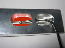 A Bent Stem Ball Gage is Used to Measure a "Hard To Get To" Internal Cavity.
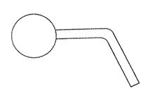 An A.G.D.S. ( American Gage Design Standard ) handle is supplied at no additional cost.
"A" - The standard size tolerance for the ball is ± .0001" ( ± .00254 mm ) The roundness or sphericity of the ball is 25 millionths of an inch (.000635 mm) maximum. The surface finish of the ball is less than 1.5 microinches ( 38 NM ) Ra.Finer Tolerance can be supplied on special order.
"B" - The stem length listed is standard, any stem length up to 6" ( 152.4 mm ) will be provided at no additional cost.
"C" - The diameter listed is standard, any reasonable diameter will be supplied at no additional cost.
"D" - The angle of the Bend is held within ±2 degrees standard. Finer tolerance will require a special bid.
A-Diameter
Ball Size |
B-Dimension
Stem Length |
C-Dimension
Stem Diameter |
D-Angle
± 2 Degrees |
Prices |
| 1 -5 Pieces |
6 - 10 Pieces |
Over 10 Pieces |
| Under .050" ( 1.27 mm ) Requires Special Quote |
.050" - 0.5"
(1.3 mm - 12.7 mm) |
3.0"
(76.2 mm) |
0.032"
(.813 mm) |
± 2 Degrees |
$95.00 double |
$86.10 double |
$78.09 double |
| $53.50 single |
$49.05 single |
$45.05 single |
.5001" - .594"
(12.7 mm - 15.09 mm) |
3.0"
(76.2 mm) |
0.187"
(4.75 mm) |
± 2 Degrees |
$96.30 double |
$87.27 double |
$79.15 double |
| $54.15 single |
$49.64 single |
$45.58 single |
.5941" - .750"
(15.09 mm - 19.05 mm) |
3.0"
(76.2 mm) |
0.187"
(4.75 mm) |
± 2 Degrees |
$98.26 double |
$89.03 double |
$80.73 double |
| $50.52 single |
$50.52 single |
$46.37 single |
0.7501" - 1.0"
(19.05 mm - 25.4 mm) |
3.0"
(76.2 mm) |
0.187"
(4.75 mm) |
± 2 Degrees |
$99.72 double |
$90.15 double |
$81.53 double |
| $54.86 single |
$50.08 single |
$45.77 single |
| Over .750" Requires a special quote |
See here for Ball Gage prices.
Ball Plug Gage With One Flat Side
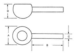 An A.G.D.S. handle is supplied at no additional cost. ( American Gage Design Standard)
"A" - The standard size tolerance for the ball is ± .0001" (± .00254 mm) The roundness or sphericity of the ball is 25 millionths of an inch (.000635 mm) maximum. The surface finish of the ball is less than 1.5 microinches (38 NM) Ra. Finer Tolerance can be supplied on special order.
"B" - The stem length listed is standard, any stem length up to 6" (152.4 mm) will be provided at no additional cost.
"C" - The diameter listed is standard, any reasonable diameter will be supplied at no additional cost.
FLAT - The dimension of the flat will be produced to your requirement. The standard tolerance for the flat is ± .002" (± .0508 mm), but a closer tolerance can be held for a small additional charge.
| A-Diameter Ball Size |
B-Dimension
Stem Length |
C-Dimension
Stem Diameter |
Prices |
| 1 - 5 Pieces |
6 - 10 Pieces |
Over 10 Pieces |
| Under .050" (1.3 mm) Requires a Special Quote |
0.050" - 0.5"
(1.3 mm - 12.7 mm) |
3.0"
(76.2 mm) |
0.032"
(.813 mm) |
$95.00 double |
$86.10 double |
$78.09 double |
| $53.50 single |
$49.05 single |
$45.05 single |
0.5001" - 0.594"
(12.7 mm - 15.09 mm) |
3.0"
(76.2 mm) |
0.187"
(4.75 mm) |
$96.30 double |
$87.27 double |
$79.15 double |
| $54.15 single |
$49.64 single |
$45.58 single |
.5941" - 1.0"
(15.09 mm - 19.05 mm) |
3.0"
(76.2 mm) |
0.187"
(4.75 mm) |
$98.26 double |
$84.72 double |
$84.72 double |
| $55.13 single |
$48.36 single |
$48.36 single |
| Over 1" Requires a Special Quote |
Ball Plug Gage with Two Parallel Flats
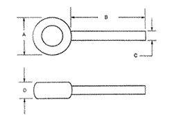 An A.G.D.S. ( American Gauge Design Standard ) handle is supplied at no additional cost.
"A" - The standard size tolerance for the ball is ± .0001" (± .00254 mm) The roundness or sphericity of the ball is 25 millionths of an inch (.000635 mm) maximum. The surface finish of the ball is less than 1.5 microinches (38 NM) Ra.Finer Tolerance can be supplied on special order.
"B" - The stem length listed is standard, any stem length up to 6" (152.4 mm) will be provided at no additional cost.
"C" - The diameter listed is standard, any reasonable diameter will be supplied at no additional cost.
FLAT - The dimension of the flat will be produced to your requirement. The standard tolerance for the flat is ± .002" (± .0508 mm) but a closer tolerance can be held for a small additional charge.
A-Diameter
Ball Size |
B-Dimension
Stem Length |
C-Dimension
Stem Diameter |
Prices |
| 1 - 5 Pieces |
6 - 10 Pieces |
Over 10 Pieces |
| Under .050" Requires Special Quote |
.050" - 0.5"
(1.3 mm - 12.7 mm) |
3.0"
(76.2 mm) |
0.032"
(.813 mm) |
$113.00 double |
$102.30 double |
$92.67 double |
| $ 62.50 single |
$ 57.15 single |
$52.34 single |
0.5001" - 0.75"
(12.7 mm - 19.05 mm) |
3.0"
(76.2 mm) |
0.187"
(4.75 mm) |
$114.30 double |
$105.24 double |
$95.32 double |
| $ 63.15 single |
$ 57.74 single |
$ 52.86 single |
.7501" - 1.00"
(19.05 mm - 25.4 mm) |
3.0"
(76.2 mm) |
0.250"
(6.35 mm) |
$119.72 double |
$108.35 double |
$98.11 double |
| $ 65.86 single |
$ 60.18 single |
$ 55.06 single |
| Over 1" Requires a special quote |
See here for Ball Gage prices.
Flexible Ball Gages
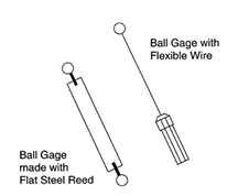
There are two general designs of flexible ball gages. The first and by far the most common flexible ball gauge is a precise ball of the desired size with a length of piano wire glued into a close fitting hole that has been drilled into the ball by the Electrical Discharge Machining process. The flexible wire can be any desired length. This design will obviously be equally flexible in all directions. This is the least expensive approach.
The second design has the gage ball fixed to a thin flat reed of spring steel. The characteristic that sets this design apart is that the position of the ball is extremely flexible in one plane and perfectly rigid in a plane 90 degrees to that. In this way, the ball can be guided between the gap to be measured without any binding. This is a much better design for long flexures.
The ball can be attached in several ways. On larger balls the narrow slot can be machined into the ball using a wire E.D.M. machine and the ball is glued on with high strength epoxy glue.
An alternative is to drill a hole in the ball and glue it onto a cylindrical pin that is then slotted with the wire E.D.M. machine. Then, this is glued on the flat spring steel reed. We stock flat flexures in ¼ inch (6.4 mm) and ¾ inch (19 mm) widths that are 0.012 inch (0.3 mm) thick.
With all of the extra work involved in this design, it is obviously a more expensive product.
See here for Ball Gage prices.
Large and Extra Long Ball Gages
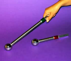

Measuring Internal Threads with Balls
Precision Balls as Measuring Tools
Internal threads are a difficult feature to measure. Thread plug gages are expensive and when special pitch diameter gages are required the delivery of the gage can be measured in weeks. Special pitch diameters are required when preparing internal threads for plating, hard anodizing or dry film lubricant and for installing threaded inserts.
Precision balls of the same diameter as the best wire size for the thread being measured can be used with cylindrical plug gages to accurately measure the pitch diameter of internal threads. Petroleum jelly can be mixed with the smaller diameter balls to hold them in the pitch diameter of the thread. and anhydrous lanolin can used to hold the larger diameter balls in place.
A good number of balls should be applied all the way around the thread. For most common threads the balls used are very small in diameter and quite inexpensive. The evaluation of the pitch diameter is made by inserting a progressively larger series of cylindrical plug gages into the gap between the pitch diameter of the thread and the opposite side of the balls. A point will be reached when one cylindrical plug gage will slip right through the gap but the next larger plug will not even start. Using this method the pitch diameter of quality threads can be determined within .0002 of an inch. This method is a little messy but it is safe, it is inexpensive,it is very accurate, and most of the best wire size balls can be supplied directly from stock.
Determining the True Position of Threaded Holes
Another excellent application of this technique is to determine the exact positional location of the pitch diameter of a threaded hole. The same basic technique is used but the largest cylindrical plug gage to fit is left protruding from the hole. This cylindrical plug gage will define the true axis of the thread including the squareness. Its position is then determined by a coordinate measuring machine, micrometer, calipers or with a height gage on a surface plate (see Figure 2.).
To prevent the cylindrical plug gage from slipping all the way through a threaded hole in the test part, place an "o" ring around the plug gage about 3/8 of an inch (9.53 mm) from the end (see Fig. 2)
See here for Ball Gage prices.
Tube Gaging System - The SnakeBall©
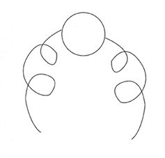 Snake Ball
If you need a black and white, go-no go system for evaluating the inside diameter of any tubing, try a “SnakeBall”©. By coupling a cable or wire to a very hard alloy steel ball that is precision lapped to the precise minimum diameter of the tube, a go no-go situation is created.
To prevent the gage ball from getting stuck somewhere in the tube, there is a coil of wire or cable on each side of the ball that is longer than the length of the tube. Using this approach, the ball can be pulled into the tube; and then pulled back out if the tube if it is undersized or dented somewhere along the path.
A cable with a colored plastic coating, can be supplied that will identify different diameters of ball. Frequently the no-go gage, will be a simplestandard ball plug gage on an AGS handle.
See here for Ball Gage prices.
Gage Tips — Spherical Indicator Tips — Sperical Gage Tips — Ball Gage Tips
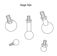
Producing one of a kind or small quantities of spherical gage tips by conventional machining is a difficult and expensive proposition. Setting up a machine to produce a high quality tiny thread against a shoulder is challenging. It is desirable to have the thread made of a hard stiff material, but machining such a material straight, concentric, and with a good thread forms in a tiny #4-40 or #2-56 thread is an expensive proposition.
The solution is simple, and it's inexpensive. By drilling a small concentric hole in a hard steel or tungsten carbide ball by Electrical Discharge Machining (EDM) and gluing in a length of high quality rolled threaded stock, the problem is solved.
To further enhance the design, a precision nut is added on the top of the ball. If required, a cylindrical spacer can be inserted between the top of the ball and the nut. The design is quite rugged, as the epoxy glue used in the assembly is a ceramic filled material, with a shear strength of 3000 pounds per square inch.
In addition, the axial load developed by screwing the tip onto the gage is applied between the nut and the thread, but not in the glue joint between the ball and the thread. The measuring force is 100% compressive stress, so there is no tendency to pull the assembly apart in every day use.
The average cost of a ball gage tip is $63.00.
The Gono™ Ball Plug Gage is much more than a cute idea
By placing the go and no go ball gage on a common shaft, that is mounted in a single handle, both the speed and accuracy of the gaging process, are dramatically improved.
When this technique of placing both Go and No Go gage elements, was tried with cylindrical plug gages on a common handle it was a gross failure. Making this type gage is prohibitarly expensive, because both squareness and concentricity between the two cylindrical elements must be perfect, but perfect is not possible. The two cylindrical elements were ground on common centers, by a cylindrical grinder. So, from the beginning you are limited to the geometry and surface finish of the grinding process.
The resulting metallurgy of the ground only cylinders is an amorphous layer of smeared metal, that all but wipes away with the slightest use. (see The story of Super Finishing by [Dr. Swigart).
The significant difference with the Gono™ Ball Plug gage is based on the fundamental principal, that there is one and only one point in three dimensional space, that defines the axis of a sphere. For this reason a common axis of rotation will automatically exist between any two spheres regardless of mounting and the axis of alignment between them is only limited by the spherical geometry of the two balls.
we need the customer to supply the go and no go ball diameters, the distance between the 2 balls and the overall length of the stem that holds the balls. There is no premium cost for this gage design. The cost is exactly the same as a standard two element Ball Plug Gage. The extra cost of drilling one hole all the way through one ball and producing a custom stem, is off set by the less expensive single ended handle for the gage.
Flaw Evaluation with Small Spherical Probes — Ball Scribe — Ball Probe — Scratch Probe — Ball Pencil
By applying the end of a given spherical tipped probe across a flaw in a machined or ground surface the proportions of individual imperfections can be evaluated.
The evaluation is conducted by mechanically scanning across the flaw with a hand held probe. If the spherical tip penetrates the flaw by any appreciable amount, a very evident click will be felt. If the radius of a given spherical tip does not penetrate the flaw, but instead spans it, there will be no noticeable click and the part is acceptable.
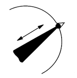 If the spherical tip drops into a flaw, the probe will move up and down, and a distinct click will be felt.
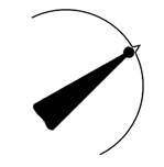 If the spherical tip spans the flaw, no click will be felt.
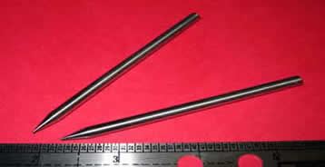 Pencil Ball Gage, Used for Flaw Evaluation
The conventional spherical probe diameters are 0.020 inch, which is 0.5 mm, or 0.04 inch, which is one mm diameter, and 1/16 inch, which is one and one half millimeter diameter, but somewhat smaller and much larger spheres are also being used. Other common diameters used are:
| Diameter |
| English |
Metric |
| 0.150" |
0.00059 mm |
| 0.20" |
0.0078 mm |
| 0.320" |
0.00126 mm |
| 0.050" |
0.00197 mm |
| 0.6250" |
0.00246 mm |
It is of great significance that it is the spherical radius of the test probe that is used, as the sensor element, so that the initial contact surface is only one half the spherical diameter. Then only a small cord of the spherical radius senses the void that constitutes the flaw, so the overall sensitivity of this system is many times greater than might be expected.
The useful life of these test probes is greatly enhanced by supplying the spheres made with tungsten carbide material. This cermet is very hard with a wear resistance that is 30 times that of hard steel.
Because of their small diameter, it is important that the balls be tenaciously attached to the probe handle so they will not be picked off. This attachment is best accomplished by brazing the ball, in place, on the probe tip. Although this task on such small balls would normally be considered impossible, we have mastered the technology to accomplish it. The probe itself is made of highly corrosive resistant metal that can be polished for clean room compatibility.
These flaw evaluation tools may be used to test chips, cracks, dents, dings, nicks, scratches, as well as scars, scrapes and chatter. These gages may be used for chip evaluation, crack evaluation, dent evaluation, ding evaluation, gouge evaluation, nick evaluation, indentation evaluation, scar evaluation, scrape evaluation, and shatter evaluation. This technique has been in use since at least the 1940's.
This viable and economical non-destructive testing method can detect surface discontinuities and fatigue cracks that the naked human eye is not sensitive enough to see. Early detection of fatigue can prevent costly teardowns.
It is much less expensive and better suited to field work than a laser evaluation system. These items are made to order. Price and delivery will be quoted.
Ball Scribe Flaw Evaluation — Ball Probe Flaw Evaluation — The Flaw Validation Block
Today flaw detection went from a bungling art to a traceable science. Previously there had been no traceable artifact to validate the effectiveness of the ball scribe test method. To begin with, the process of tracing a handheld spherical-tipped probe, or scribe, over a surface to evaluate flaws such as cracks, scratches, and other blemishes is inherently subjective. The results of this procedure can vary from one individual to another unless all technicians have been properly trained and their individual sensitivity or feel measured against a standard. Without testing the sensitivity of an individual their performance can be unsatisfactory.
We now have a certified test master with which to train individual technicians, and finally we have a method of testing each individual’s ability to actually detect flaws.
The Flaw Validation Block consists of two individual pieces of stainless steel that are hardened to 58H.R.C. minimum for long service life. The adjacent faces of these hardened stainless steel pieces are precision-ground and lapped flat within one light band (11.6 microinches). These two precisely finished pieces are separated by a precision spacer, which determines the width of the gap between them. This precise gap is used to simulate the flaw.

A small extension of this precision spacer is allowed to protrude out the back side of the artifact, so that traceability of this artifact can be validated periodically. The two pieces are rigidly bonded together by a tie rod that goes through its center.
The working surface of the flaw validation block is precision ground and flat lapped to provide a perfectly continuous flat surface to better define the gap. The two piece assembly is then epoxy glued into a base plate. This base plate provides added protection, giving better mechanical stability and provides greater mass. The width of the gap as well an individual serial number are laser engraved on the side face of the Flaw Validation Block.
Single Element Go No Go Ball Gages — Dual Functioning Ball Plug Gage
The single element go, no go gage, is an interesting take off on the standard Ball Plug gage. The go ball gage is located on the end of a, rather long, small diameter stem. There is a space and then the no go gage is positioned further down on the same stem. On first thought, you would think that the, no go gage ball , would have to be absolutely concentric to the, go gage ball, or that any eccentricity between them would cause the balls to bind up in the part.
This is not the case at all. The center, or axis, of a ball, unlike any other geometry is defined by a single point in three dimensional space. What this means is that the two balls only have to be located, in the ball park and that any small eccentricity will have zero effect on the function of the gage. When a large number of parts must be measured, this little twist can save half of the inspection time. This design is not any more expensive than a simple go, no go ball plug gage. The extra cost of drilling the hole all the way through one ball is made up through savings on the cost of the single handle.